Bienvenido a Sedecal
Conforme a la Ley 29/2006 de 29 de julio 2006 para acceder a nuestra página web, le rogamos que nos confirme que usted es un profesional sanitario.
Gracias de antemano.
- SI
- NO
Conforme a la Ley 29/2006 de 29 de julio 2006 para acceder a nuestra página web, le rogamos que nos confirme que usted es un profesional sanitario.
Gracias de antemano.
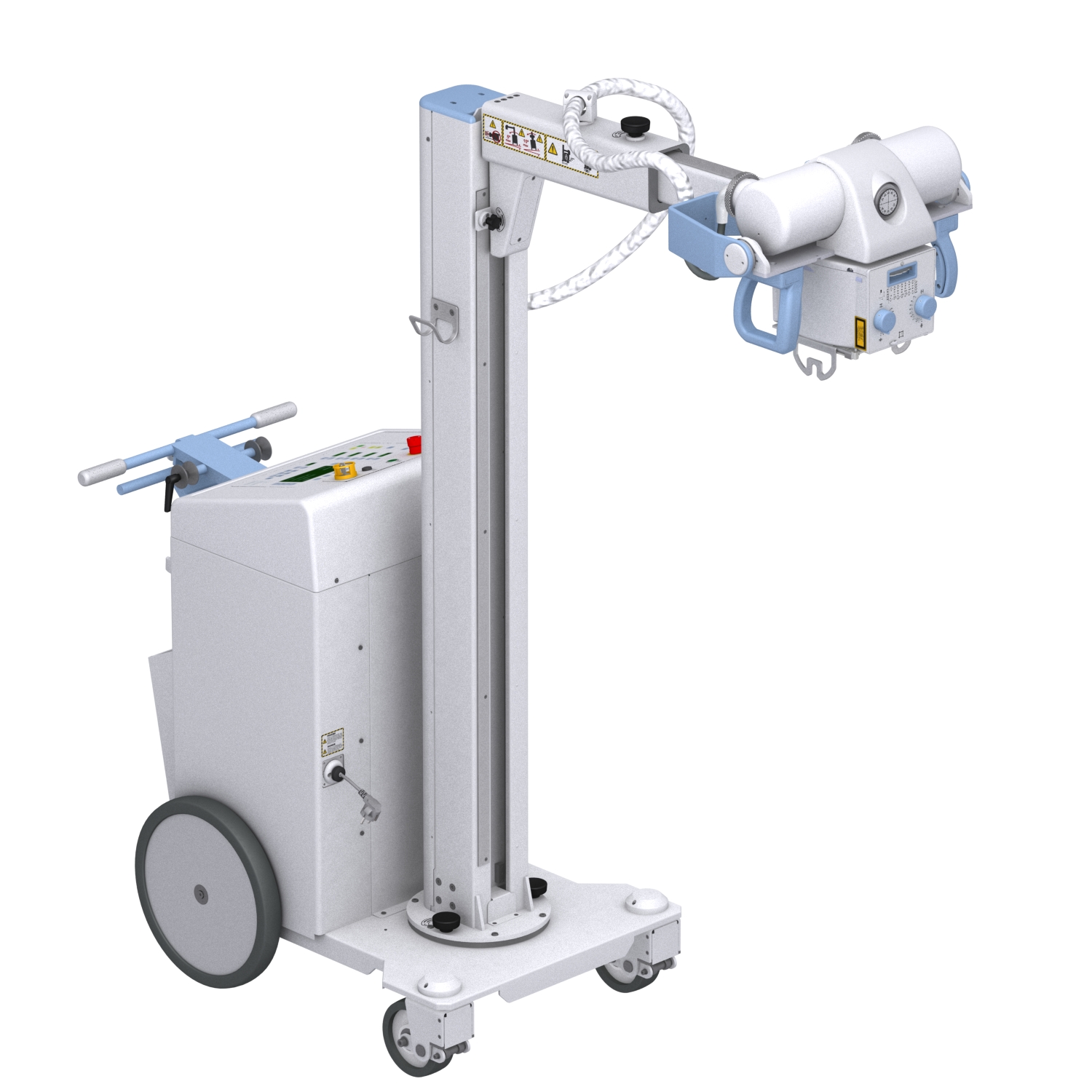

The mobile radiographic system, with Capacitor Discharge Generator, allows us the manoeuvrability and operability that the new Clinics and Hospitals demand.
The Capacitor Discharge Generator has the most innovative technology for the High Frequency X-ray Generator, which permits high constant output power from any standard power socket in any Clinic or Hospital area, Operating Rooms, Intensive Care, Emergency, etc.
Its low ripple factor and high accuracy of the radiographic parameters (kVp, mA, exposure time), reduce soft radiation and improve the X-ray beam homogeneity allowing an improvement in the image quality and a reduction of the patient dose.
Under normal operating conditions, the Storage Capacitors are kept at an optimum charge level by the Capacitor Charger which controls the level and performs periodical charges.
Output powers available: 16, 20 and 32kW.
Generator with multiple advanced functionalities:
| GENERATOR | |
|---|---|
| GENERATOR TYPE | SINGLE PHASE, CAPACITOR ASSISTED, HIGH FRECUENCY. 1 TUBE |
| FRECUENCY | 50/60kHz |
| MAXIMUN POWER kW | 20KW, According to IEC definition IEC (0.1s, 100Kv) |
| MÍNIMUM POWER | 0.4 KW (4kVp 10 mA) |
| kVp RANGE | From 40kVp to 150KVp. In steps of 1KVp |
| mAs RANGE | From 0.1mAs to 500mAs in 18 steps, Renard10 Scale. |
| mA RANGE | From 10 mA to 500 mA in 15 steps, Renard10 Scale. 10,12.5,16,20,25,32,40,50,63,80,100,125,160,200,250,320,400,500 |
| EXPOSURE TIME RANGE | 1.0msec, From 1.0msec to 10,000msec (0.001 to 10 seconds) |
| POWER OUTPUT (@ 0,1s) | 200 mA @ 150kVp 250 mA @ 128kVp 320 mA @ 100kVp 400 mA @ 80kVp 500 mA @ 64kVp |
| RIPPLE FACTOR | 1 % |
| MARGING OF ERROR - KVP & MA/ TIME | Lower than 5% in all parameters |
| POWER LINE OPERATION & POWER SUPPLY | 100 / 110 / 120 / 208 / 230 / 240 ± 10%Vac. Adaptation for local conditions from 8 to 16 A. |
| ENERGY STORAGE CAPACITY | 14,000 Joules |
| CHARGING TIME | ? Maximum 4 seconds for a line of 230 VAC with selection of 16 A in the Generator; or maximum 40 seconds for a line of 110 VAC with selection of 8 A in the Generator. ? During X-Ray exposures. ? Every 150 seconds. |
| LINE IMPEDANCE | LINE IMPEDANCE Due to the unit is a Capacitors Assisted Generator, a specific value of Line Impedance is not required. |
Images can be obtained with the patient in the sitting, standing or lying position. Examinations can be performed to any kind of patient group. Patients may be physically able, disabled, immobilized or in a state of shock.
X-ray image receptor types that can be used with this equipment: Cassette with Film, CR (Computed Radiography) or Digital Detector.
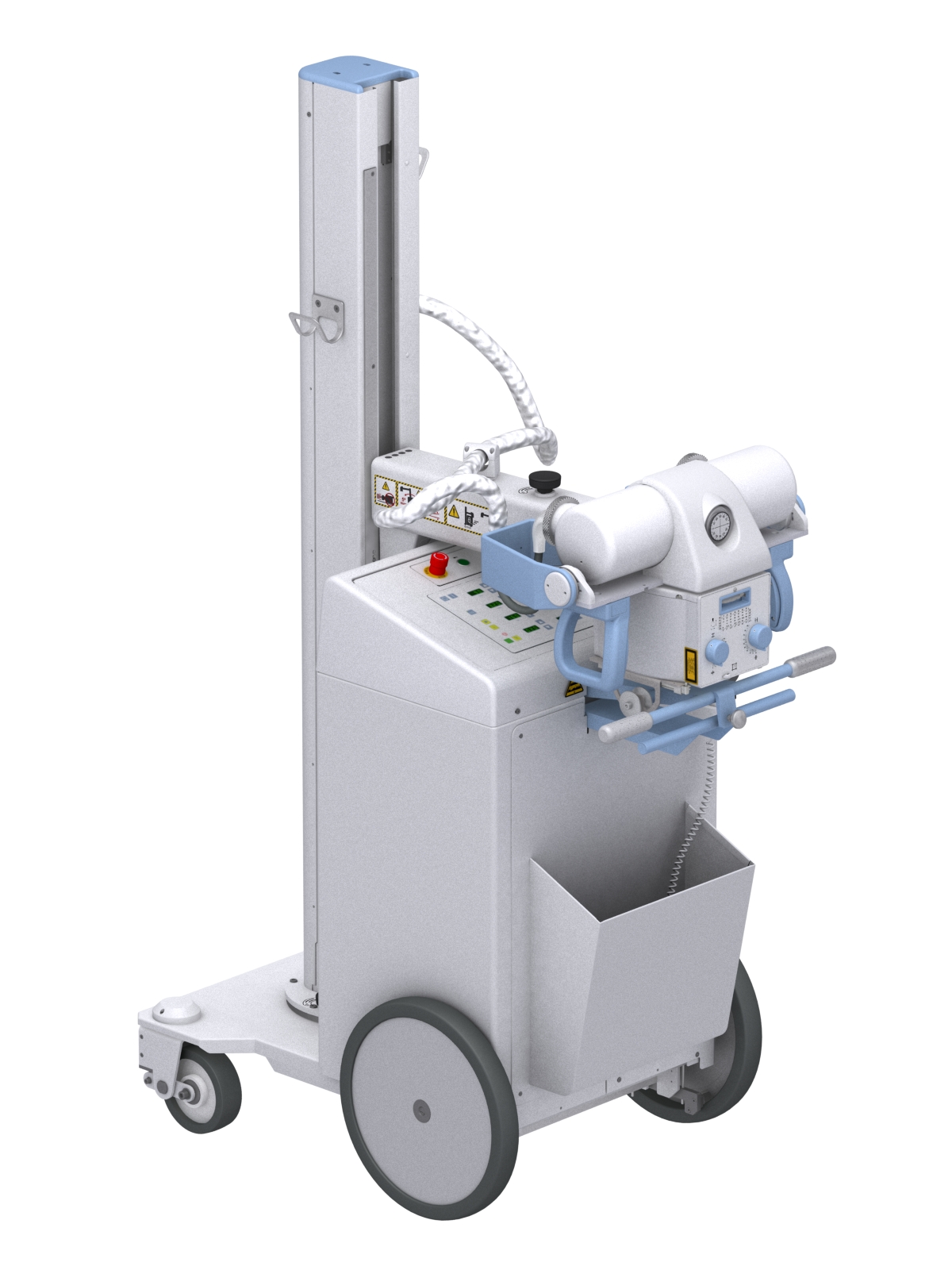
Excellent mobility, large rear wheels, allowing easy handling and even overcoming small obstacles. Easy access through doors, elevator, corridors, bedside patient areas, etc.
Perfectly counterbalanced tube arm for easy and comfortable movement.
CONTROLS FOR POSITIONING OF THE TUBE-COLLIMATOR ASSEMBLY: Both Handgrips of the Tube-Collimator Assembly allow the vertical and telescopic Arm movements to place it in relation to the position of the patient.
ARM VERTICAL LOCK: with the lock lever.
ARM LONGITUDINAL LOCK, telescopic travel: with the lock lever.
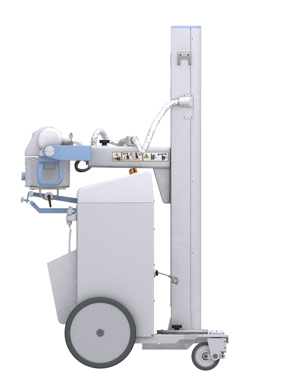
PARKING POSITION:
The parking position of the unit provides a safe and easy motion and transport. Insert the Arm and rotate the Column until the mobile is positioned as shown on the left image. Then block it just like the other locks for Tube-Collimator Assembly, Arm and Column with the corresponding Lock-Levers.
DISPLACEMENT CONTROLS:
The only displacement controls of the Unit are the Front Handle Bar, the Brake Control Bar and the Blocking Button. The brakes are released by gripping and holding the Brake Control Bar towards the Front Handle Bar. The Unit is manually moved pushing or pulling it from both Bars. The front steering wheels and the back main wheels provide comfortable driving as well as easy positioning of the Unit.
The Unit is also provided with a Blocking Button that keeps brakes released for longer distances. Grip Front Handles and press Blocking Button to release brakes and start motion.